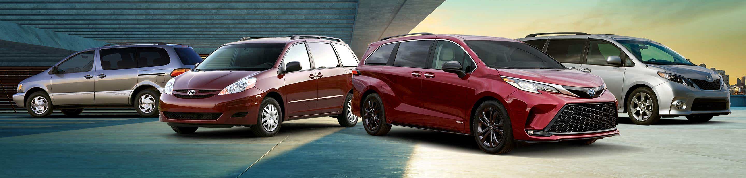
Toyota Sienna Forum - siennachat.com banner
341 - 360 of 435 Posts
Discussion starter · #341 · (Edited)
With the front seat mounting bolts removed and the rear bolts loosened, gently tilt the seat frame back and slide the Jackers under the front mounting points. Be sure to orient all components in the correct direction. The machined nubs and indentations on the Jackers aid in sliding the shims together for proper fitment:
Image


Before applying blue Loctite to the new 60mm mounting bolts and torquing them into position, I slowly finger tightened them 5-6 rotations to ensure the threads were clean and everything was properly aligned to mitigate the risk of cross-threading:
Image
Image
Image


Blue (removable) Loctite applied to the new, 60mm, hex head mounting bolts:
Image


Hardware torqued down to 27-foot-pounds:
Image

Image


Trim pieces reinstalled and the finished product:
Image
 
Discussion starter · #342 · (Edited)
With the driver seat completed, I moved over to the passenger side.

Seat Jackers installed under the passenger seat:
Image
Image


An ingenious feature of the Seat Jackers is a threaded hole at the leading edge of the bottom shim. Desert Does It offers a line of mounting panels that utilize these holes to facilitate additional storage in the dead space directly in front of the seat. This is not something I’m going to pursue right now, but may explore in the future:
Image
Image


Here are the before and after shots of the driver seat (passenger seat results are the same). An angle finder was placed in the seat to quantify the improved seating angle in degrees.

*note - after the fact I realized that the angle finder wasn’t placed in the exact same spot on the seat cushion for each photo. I should’ve marked the spot with some painters tape to ensure the placement was consistent. This error throws the reading off by a few degrees, but the angle finder does illustrate that the seat angle is altered by the Seat Jackers.

Before:
Image
Image


After:
Image

Image


—-

In conclusion, both my wife and I are very pleased with the finished product and this is something I wish I would have done sooner. The difference in seating position and comfort is night and day. Before the Jackers, I felt like I was sitting on top of the seat and sliding forward; after the installation, I feel like I’m actually sitting in the seat - it reminds me of what you’d experience in a racing/performance seat. The seating position feels much more planted with a better, more commanding view of the road. If you have longer legs or are taller, I think you’ll find the thigh support is vastly improved, which makes the seats much more tolerable for longer drives.

Also, a big thanks to the guys at Desert Does It for answering my questions along the way.

Cheers,

☕ 😎
 
And finally, some nighttime photos of the lights in action. These shots are from my driveway and there are some streetlights in the distance, but my driveway is pretty dark when my exterior garage lights are turned off. These photos are a pretty good representation of the illumination offered by these lights - they are bright and illuminate not only the rear cargo area very well, but also light up the area directly below and around the rear hatch. I'm very satisfied with the product and the utility offered by this modification.

Both lights illuminated:
View attachment 65213 View attachment 65215 View attachment 65214 View attachment 65216

Only the right light illuminated:
View attachment 65217

A few final thoughts - again, this was a modification that took some time to complete correctly, but the final product was well worth it. If one was to use the supplied jumper harness, you'd be looking at a much shorter install time (probably around 1.5-2 hours).

I like that the lights can be illuminated independently from one another, and the quality seems to be on par with an OEM part. A normal use case for these lights may be when we're loading gear or kids into the back of the van; when you're in a hurry, it's nice to be able to reach up and tap one light (which is more than enough to light up the rear area of the vehicle). But the second light is there if you need it.

And I really like the fact that there are two lights spaced rather far apart from one another. This minimizes shadows that could darken the cargo area while loading/unloading the van.

I hope this helps anyone considering a similar install. This modification is so functional, it's a shame Toyota didn't offer it from the factory.

Cheers, 🍻
Hi Yonah, big project! Side question to ask you regarding the main fuse at the positive terminal of the aux battery terminal:

Image

1. I am going to mount my own 1500 watt inverter at this terminal intending to draw up to about 125 amps (car power switch on the ON position). I will have a 150 amp breaker mounted inline on my red cable going to the positive terminal of the aux battery. I think it does not matter if I connect the red cable before or after the vehicle's main fuse (that is, right at the battery terminal at the stud pointing upward, or where the long cable from the 'alterntor/hybrid inverter in the front' is connected to the "receiving/mounting" terminal(facing me) at the main fuse.) Your thoughts?

2. Do you happen to know how many amp is that main fuse.
 
Discussion starter · #344 ·
Hi Yonah, big project! Side question to ask you regarding the main fuse at the positive terminal of the aux battery terminal:

View attachment 69370
1. I am going to mount my own 1500 watt inverter at this terminal intending to draw up to about 125 amps (car power switch on the ON position). I will have a 150 amp breaker mounted inline on my red cable going to the positive terminal of the aux battery. I think it does not matter if I connect the red cable before or after the vehicle's main fuse (that is, right at the battery terminal at the stud pointing upward, or where the long cable from the 'alterntor/hybrid inverter in the front' is connected to the "receiving/mounting" terminal(facing me) at the main fuse.) Your thoughts?

2. Do you happen to know how many amp is that main fuse.
1. I'm having some difficulty picturing this in my head, can you sketch it out?

2. The amp rating of the fuse should be printed on it. Does you Sienna have this fuse installed, or are you planning on adding it?
 
1. I'm having some difficulty picturing this in my head, can you sketch it out?

2. The amp rating of the fuse should be printed on it. Does you Sienna have this fuse installed, or are you planning on adding it?
Thanks Yonah! I am picking your brain and see if you come across some knowledge for my questions when you were doing your mod on the Rear Hatch / Cargo LED Lights.

Instead of a sketch, I will use a photos since it is not that complex. I am trying to duplicate the 1500 watt AC outlet function your Platinum has but the 'Toyota Chicago region' would not spec out all the XLE's with that legit option. (i.e. In this discussion, we are now looking at this: your OEM/my aftermarket 12V DC to 110 VAC inverter is powered by the hybrid battery power, but after the DC to 12V DC step down inverter in the engine compartment. I will not have your logic circuit to force you to have the key in the ON position before using the function and in my case, I have to trust my human logic/brain to remember to have the key in the ON position before letting the inverter dry up my little aux battery in no time. I will therefore tap into the positive battery terminal and actually drawing the amps from that thicker than expected black cable that looks like #0 gauge.)

Similar to your Platinum, mine also already has a MAIN fuse on the connection end of the positive battery cable. You are right, the Amp specs are on the cover. It was too dark yesterday, and I missed them. 140 A for output to accessories and 220 A for input to the battery (I cannot imagine it ever will draw that much anywhere close to 220A because it is not powering engine starting on Hybrids. I vaguely remember someone mentioning your OEM DC to AC inverter is also tapping into this cable, not sure if it is at this connection area at the battery though. The photo of your main fuse does show more thing but those may be added in by your mod, I have not read your writeup to figure that out.)

Image
Image


The layout('sketch') is this mock up below and I have yet actually connected them to the battery. The little thing in line is a 150 AMP circuit breaker(also kill switch).
Image


The black negative cable(2 AWG / #2 gauge) will be grounded at the negative battery terminal. No further comment on that.
Image


My question to pick you brain is on the next two photos pertianing to whether my inverter's red/positive cable (2 AWG) should be 'connected to the battery' before or after the battery Main fuse.

My thinking it, it does not matter much. I will occassionally run my inverter at the max 1500 watt AC continuous power (intermittent/surge wattage at appliance start up may be 2800 watt or so) therefore the continous amp on the inverter 12V DC input side will be around 140 A. The input side is protected by my 150 A breaker. 150A is way below the MAIN fuse's 220A spec therefore connecting this way is almost like the MAIN fuse is not existing.

In theory, connecting after the fuse let the MAIN fuse act as a backup fuse, and that is not bad, but I will risk an unexpected burning up of that 220A fuse due to unexpected reason can leave me strained in some place close to nowhere.

Actualy, that also point back at what is Toyota's purpose of having that 220A fuse and for that power cable. The small AUX battery can deliver 220A for a short time. So, is that fuse a fail safe prevention for any mistake that unexpected drawing down that aux battery at that high an amperage to fast rather than for protecting of shorting or grounding or whatever is taped into it along that power cable?

Please also kindly look at your Platinum hookup to see if there is connecting cable from that area back to you OEM DC to AC inverter (I believe that in the front of the vehicle). I also vaguely recall somewhere someone mention a white cable (on a Highlander with the 1500 Watt AC option).

Thanks. By the way, yesterday I listed up the comments from my call to Firestone on the Firestone thread.

Option 1: Connect right on top of the battery terminal (after the MAIN fuse).
Image


Option 2: Right at the connection point of the 12V supply to the battery (therefore before the MAIN fuse)
Image
 

Attachments

Discussion starter · #346 ·
Thanks Yonah! I am picking your brain and see if you come across some knowledge for my questions when you were doing your mod on the Rear Hatch / Cargo LED Lights.

Instead of a sketch, I will use a photos since it is not that complex. I am trying to duplicate the 1500 watt AC outlet function your Platinum has but the 'Toyota Chicago region' would not spec out all the XLE's with that legit option. (i.e. In this discussion, we are now looking at this: your OEM/my aftermarket 12V DC to 110 VAC inverter is powered by the hybrid battery power, but after the DC to 12V DC step down inverter in the engine compartment. I will not have your logic circuit to force you to have the key in the ON position before using the function and in my case, I have to trust my human logic/brain to remember to have the key in the ON position before letting the inverter dry up my little aux battery in no time. I will therefore tap into the positive battery terminal and actually drawing the amps from that thicker than expected black cable that looks like #0 gauge.)

Similar to your Platinum, mine also already has a MAIN fuse on the connection end of the positive battery cable. You are right, the Amp specs are on the cover. It was too dark yesterday, and I missed them. 140 A for output to accessories and 220 A for input to the battery (I cannot imagine it ever will draw that much anywhere close to 220A because it is not powering engine starting on Hybrids. I vaguely remember someone mentioning your OEM DC to AC inverter is also tapping into this cable, not sure if it is at this connection area at the battery though. The photo of your main fuse does show more thing but those may be added in by your mod, I have not read your writeup to figure that out.)

View attachment 69387 View attachment 69388


The layout('sketch') is this mock up below and I have yet actually connected them to the battery. The little thing in line is a 150 AMP circuit breaker(also kill switch).
View attachment 69390

The black negative cable(2 AWG / #2 gauge) will be grounded at the negative battery terminal. No further comment on that.
View attachment 69391

My question to pick you brain is on the next two photos pertianing to whether my inverter's red/positive cable (2 AWG) should be 'connected to the battery' before or after the battery Main fuse.

My thinking it, it does not matter much. I will occassionally run my inverter at the max 1500 watt AC continuous power (intermittent/surge wattage at appliance start up may be 2800 watt or so) therefore the continous amp on the inverter 12V DC input side will be around 140 A. The input side is protected by my 150 A breaker. 150A is way below the MAIN fuse's 220A spec therefore connecting this way is almost like the MAIN fuse is not existing.

In theory, connecting after the fuse let the MAIN fuse act as a backup fuse, and that is not bad, but I will risk an unexpected burning up of that 220A fuse due to unexpected reason can leave me strained in some place close to nowhere.

Actualy, that also point back at what is Toyota's purpose of having that 220A fuse and for that power cable. The small AUX battery can deliver 220A for a short time. So, is that fuse a fail safe prevention for any mistake that unexpected drawing down that aux battery at that high an amperage to fast rather than for protecting of shorting or grounding or whatever is taped into it along that power cable?

Please also kindly look at your Platinum hookup to see if there is connecting cable from that area back to you OEM DC to AC inverter (I believe that in the front of the vehicle). I also vaguely recall somewhere someone mention a white cable (on a Highlander with the 1500 Watt AC option).

Thanks. By the way, yesterday I listed up the comments from my call to Firestone on the Firestone thread.

Option 1: Connect right on top of the battery terminal (after the MAIN fuse).
View attachment 69392

Option 2: Right at the connection point of the 12V supply to the battery (therefore before the MAIN fuse)
View attachment 69393
To be honest, I'm not entirely sure what that 220A fuse protects. My assumption is it feeds the 12v circuitry powered by the starter battery (interior lights, power outlets, ECM, etc.).

If I were going to add an inverter like the project you're undertaking, I would leave the OEM electrical system intact and not add the inverter (or any accessory) to that fuse. Like you mentioned, overloading (and blowing) that fuse would likely leave your van deadlined until a new 220A fuse could be sourced. I would add a set of accessory battery terminal blocks and create my own accessory circuit. Similar to what I did in my own van, here:


Photo of the SDHQ brand Toyota-specific battery terminals that I used is below. These terminals afford the attachment of additional cabling (to build accessory circuits) without impacting the OEM connections, fuses, etc.:
Image


And here is the product link:
SDHQ Built Complete Billet Battery Terminal Kit (sdhqoffroad.com)

As you can see, I added a dual-fuse MRBF fuse block to the positive terminal (component with the red isolation cap attached). If I were in your position, I would add the SDHQ terminals (or something similar) and then a single MRBF fuse block (or double, to give you some flexibility in the future if you want to add more accessories). Then connect invertor to the MRBF fuse terminal and the negative cable to one of the mounting locations on the SDHQ negative terminal block.

MRBF fuse block:
MRBF Terminal Fuse Block - 30 to 300A - Blue Sea Systems

Here's a link to the 150A MRBF fuse, which would cover your invertor's 140A requirement:
MRBF Terminal Fuse - 150A - Blue Sea Systems

If 150A is not enough, Blue Sea produces MRBF fuses up to 300A:
Marine Rated Battery Fuses - Blue Sea Systems

You could still mount the circuit breaker inline between the fuse and your inverter, but IMO it would be redundant and the only real benefit is it gives you a kill switch (manual override) to disconnect the invertor from the 12v battery.

I hope this helps.
 
Tks. Your approach makes sense. I will study your info some more.

By the way, didn't your 2023 come with the OEM MAIN/battery fuse(2)? I notice you have replaced the factory battery with the DieHard and I imagine that is to offer you more capacity to run lights and accessories with the engine not running. I looked at your photos again just now. Did you do away with that whole MAIN fuse (with the two fuses) and put in your Blue Sea system and obmit the 220A or they are actually still there under the red cover and mounted onto the SDHQ block?
 
Discussion starter · #348 ·
Tks. Your approach makes sense. I will study your info some more.

By the way, didn't your 2023 come with the OEM MAIN/battery fuse(2)? I notice you have replaced the factory battery with the DieHard and I imagine that is to offer you more capacity to run lights and accessories with the engine not running. I looked at your photos again just now. Did you do away with that whole MAIN fuse (with the two fuses) and put in your Blue Sea system and obmit the 220A or they are actually still there under the red cover and mounted onto the SDHQ block?
Yeah, I replaced the OEM lead acid battery with an AGM unit for greater deep cycle capacity.

I didn’t omit any part of the OEM electrical system. They OEM fuses are still there. My fridge is installed at the moment, which makes accessing the battery difficult, but I’ll snap a photo once I remove the fridge in a couple of weeks. We’re getting ready to hit the road for a big road trip.
 
Discussion starter · #349 · (Edited)
Armrest (by Primo Workz)

In an effort to continue improving driver comfort, I began some market research into vehicle-agnostic aftermarket armrests as I find the upper door card on the 4th Gen Sienna to be too rigid, narrow, and uncomfortable for longer drives. Primo Workz, a small business out of (I think) Virginia, produces easy-to-install armrests that are compatible with pretty much any vehicle on the road. I opted for their black ripstop product that is, per their product page, "...manufactured with a stainless steel plate covered with hard-wearing Ripstop material. All zips and sliders are Industrial Grade # 5 YKK".

Product link: Armrest - Black Ripstop – Primo Workz

After placing my order, the armrest arrived a few days later.
Image
Image


Install is a breeze, all you really need to do is slightly bend the armrest in on itself and then slide it over the top of the door card, ensuring the little lip at the top of the armrest hooks behind the upper panel. I played around with the placement and settled on the position in the below photos. As a bonus, the armrest has a little zippered pocket for small items.
Image
Image
Image


I'm happy with the end result and find the added softer and wider support significantly enhances driving comfort. The Primo Workz armrest is not only functional but also blends really well with the interior aesthetics of the Sienna - win/win.

:cool:
 
Discussion starter · #350 · (Edited)
A few days ago we hit the road for summer break; drove north through San Francisco, crossed the Golden Gate Bridge and then up Hwy 1 to Northern California.

Morning fog obscured the views in SF, but luckily the route was smooth and we encountered light traffic.
Image

Image
Image
Image


Winding our way up Hwy 1.
Image


We’re currently in the Redwoods National Park checking out the beaches and trails. Lots of fun 😎
 
Discussion starter · #352 · (Edited)
We spent Independence Day in and around Bend, Oregon. Breathtaking country.

Here are some photos from the trip:
Image
Image
Image

Image
Image
Image


The Last Blockbuster:
Image


Passing by Mount Shasta on the way home:
Image


The Sienna didn’t flinch. The van was loaded down with about 900 pounds of passengers and cargo and still managed ~30.5 MPG over a roughly 1,500-mile-long journey. The rear airbags were inflated between 20-35 PSI depending on how much gear we had loaded in the van - for example, when most of our luggage was unloaded and the van set up for day trips, I opted for 20 PSI to help soften the suspension.

I initially planned on mounting both the Packasport and the Stowaway hitch cargo boxes; however, after loading the van, I decided we could make due with just the roof box, so I went that route. Sometimes it’s best to keep things simple.
Image

Image


Fun trip 🏔😎
 
I had one pin break on me. I doubled up the ground (blue) wire (two leads into one pin) to make the harness simple. I didn't have the leads perfectly lined up when I crimped them and the back of the pin broke. This was one part operator error and another part crimping more wire inside of the pin than it was designed to hold - doing this required both wires to be positioned perfectly square inside of the pin before crimping. It will make sense when you see it.

I didn't sketch out the diagram, but this photo of the unit assembled, pre-conduit/wrap install, should help you visualize everything. The blue wires are ground, the white is to the CHMSL, and the red wire is from the vehicle brake light circuit (van side of the harness). The supplied instructions spell this out. I compressed the two ground wires with marine-grade heat shrink at the back of the connector to keep them positioned and secure under road vibration; probably overkill for a Sienna, but figured it was worth doing.

Photo of the module assembled:
View attachment 67980

Recap of the wire legend:
View attachment 67981
Yonah, I've followed your exact process and built the custom BLP-1 harness for my wife's Sienna. Certainly would not have known of this great mod, much less how to build the custom harness without this great thread and your detailed photos and instructions. Everything works well and love I didn't have to hack into the OEM harness/wiring. Now I also have newfound wire crimping and electrical connector building skills to boot!

Thank you!
 
Discussion starter · #357 · (Edited)
Yonah, I've followed your exact process and built the custom BLP-1 harness for my wife's Sienna. Certainly would not have known of this great mod, much less how to build the custom harness without this great thread and your detailed photos and instructions. Everything works well and love I didn't have to hack into the OEM harness/wiring. Now I also have newfound wire crimping and electrical connector building skills to boot!

Thank you!
Hopefully, this reduces the chance of someone rear-ending you. After installing the BLPs in both of my vehicles, I have noticed that drivers behind me seem to stop more quickly, with greater distance between our vehicles. It's also common to see drivers behind us get annoyed and pass (despite the van's speed) which is a win in my book. I'd rather have an aggressive driver 1/4 mile ahead of me vs. riding my rear bumper while they play with their phone and radio.

Glad you found the write-up useful and were able to gain a new skill. I appreciate the kind words! :)

For anyone curious, this is the referenced modification:

 
You know they say “Imitation is the sincerest form of flattery.”

Found this “lightly used” Stowaway 2 for $300. I didn’t need it as I have the biggest Thule Cargo Carrier for the top of my Sienna but I wanted it just in case after seeing it on yours and for the price I couldn’t resist. It looks brand new outside and in.

Image
 
Discussion starter · #359 ·
Added the Primeworkz and Seatjackers to my vehicle. It's taken a little getting used to but more comfortable. Thanks for these small mods.
The armrest is a cool mod - definitely makes the driving position more comfortable. My wife asked if I could reduce the angle of the passenger seat (provided by the Seat Jackers), but also wanted the seat to sit a little higher. I purchased another pair of Jackers and added two shims to the rear of the front passenger seat. So now it's sitting at 1.5" of lift in the front (3x shims) and 1" of lift in the rear (2x shims). This gives her a little more legroom and levels out the seat.

You know they say “Imitation is the sincerest form of flattery.”

Found this “lightly used” Stowaway 2 for $300. I didn’t need it as I have the biggest Thule Cargo Carrier for the top of my Sienna but I wanted it just in case after seeing it on yours and for the price I couldn’t resist. It looks brand new outside and in.

View attachment 69773
$300 for a clean Stowaway2 Max is a steal! Congrats on finding that kind of deal. The Stowaway has its pros/cons, but it's nice having the additional cargo space when you need it.
 
Thanks for all of this great info. Am seriously considering installing the Firestone airbags - we have the Ecohitch, spare tire, and also towing a small popup on occasion. I do have the 2" JOR lift kit installed. I am still trying to understand if there's any downside to installing? From reading through, I would not be at the point where I'd install the full integrated compressor, so would this make it something that I'd just always have to tinker with to get at the right pressure? It seems like at a minimum, it's no different than the current ride but wanted to double check my thoughts here.
 
341 - 360 of 435 Posts